2

I upgraded my Ender 3 V2 with a BIQU H2 hot end and extruder head and a BLTouch probe. I updated the firmware from Ender website using Ender-3 V2_32bit_4.2.2_BLTouch_Marlin-2.0.1 - V1.1.1.bin. All hardware seems to work flawlessly, incl. all axis movements, extruder movements, heating, fans controlling,...

However, I don't know how to really proceed with changes to extruder settings. I found no YouTube videos or internet articles, particularly about "Ender 3 V2" and "BIQU H2" and what I found is not compatible.

From what I gathered, I need to change the speed ratio of extrusion and the gear ratio of extrusion. But I don't know how to set it on Ender 3 V2. I tried to configure the gear ratio. There's a nice YT manual for Ender 3 V2, however for the old extruder, so I couldn't measure the extruded filament beyond the extruder. I made a line 100 mm above the extruder with a marker and set the extrusion to +100. I got something like 10 mm of snail-pace slow extrusion. So I went to the extruder's gear ratio and tried to raise it, but the value should be roughly $100 / 10 * 93 = 930$ (93 was the default and current value). However, the adjustment goes only to 186, and with that, I get a little bit less than 20 mm of extrusion. And I also suspect that the extruder's speed is about 7 times smaller (1:7 gear ratio) than what it is supposed to be.

So, could you advise or direct me to materials that explain how to set BIQU H2 on Ender 3 V2? Is there anything else I have to set, apart from extruder speed and gear ratio? Some tutorials mentioned about stepper motor voltage if I remember correctly, but again, that cannot be set in the menu. I'm fine with settings over G-code, as long as I have some clear instructions on what actually to set.


Note:

I marked Oscar's post as an answer, though to me it tells only part of the story. But helped to clarify some stuff. Be careful and study the matter yourself, however, you should come to this conclusion and those steps for Ender 3 V2 and BIQU H2, particularly for setting the extruder motor current.

Disclaimer: Those were my steps and I do not take any responsibility for anything if you follow them. Check everything yourself and advice in the comments below, if anything doesn't look right.

  1. Check you have TMC2208 - you should have the large letter A written on your card reader

  2. Check your BIQU H2 stepper motor nominal voltage is 800 mA in the attached manual

  3. Check the resistors at the stepper motor (marked E) on your main board are R150 (150 mΩ)

  4. If all above is true, you should get Vref = 1.05. Based on

$\frac{0.8}{\sqrt{2}} = {\frac{325mV}{150mΩ+20mΩ}*\frac{1}{\sqrt{2}}*\frac{V_{ref}}{2.5V}}$

I separated voltage:

$V_{ref} = \frac{0.8A/\sqrt{2}}{325mV/((150mΩ+20mΩ)*\sqrt{2}*2.5)} = \frac{(150mΩ+20mΩ) * 2.5 * 0.8A}{325mV} = 1.046V$

  1. Measure your current Vref with positive contact on the potentiometer and negative on the card reader cover, using an appropriate scale on your Voltmeter, i.e. up to 20V DC. You should get something like 1.4 V, if you have the default factory setting. One hint: I put a piece of insulation tape on the cooler next to the potentiometer in order to avoid a short circuit in case the cooler is connected to the negative body - it's easy to touch it with a screwdriver. Remove it after the correct voltage is set. Or use a plastic or ceramic screwdriver.

  2. Turn slightly the potentiometer anti-clockwise, about 1/5 of the circle for start, and measure the voltage again, then do a fine adjustment, measure again, etc., until you get desired value. I could set it from 0.03 to 1.02, meaning that I set 780 mA, slightly below the nominal voltage.
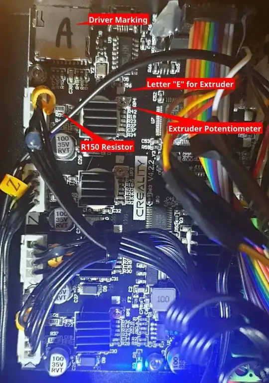
Photo of Creality v4.2.2 motherboard with parts marked for reference

Oak_3260548
  • 123
  • 1
  • 5
  • 1
    This sounds like a duplicate for the [question](https://3dprinting.stackexchange.com/questions/18876/) you already left a comment on [the answer](https://3dprinting.stackexchange.com/a/18878/) for your problem, you can use a console or use `M92 E930` in your start G-code or in a separate G-code file with `M500`. Stepper reference voltage must be set manually using a multimeter and small screwdriver, your driver's don't allow to adjust through firmware or G-code. This stepper should be limited to 0.8 A. – 0scar Oct 16 '22 at 04:23
  • Sorry, not really a duplicate, Ender 3 settings is very different from V2 in practical terms. What I would like to know are instructions specific for V2, so that I don't do guessing. I'll probably use a G code, though I'd like to see some firm instructions. I hope I'll be able find more about adjusting the stepper motor voltage too. Though both of the actions sound straight-forward, it's good to not experiment and do it right. – Oak_3260548 Oct 16 '22 at 07:23
  • As both machines run Marlin there is no difference, it is my opinion that this could be a duplicate (which I still think it is after your comment), but, the community decides. The difference is that the V2 has a TFT with separate firmware, it is that firmware that limits the inserting of higher values for your application. The answer of the other question will help you set the new steps per mm for your extruder, this is not different for the V2. The limiting of the current is a hardware solution, measure the voltage while turning the screw. – 0scar Oct 16 '22 at 09:46
  • @Oscar Thank you for hiding wrong answer. You might be right and I might be wrong, of course. I based my assumption on a YT manual, that showed how to change it in Ender 3 in Advanced Settings and it said it can't be done that way on V2 - might be exactly as you said with TFT module limiting inputs. I will use the G code, the two command are clear, hopefully there's no header or footer code required (as it is with most CNC machines). As for voltage, I put edit into my question. – Oak_3260548 Oct 16 '22 at 17:44
  • @Oak_3260548 I have tried to format your equation in your recent edit but without knowing what exactly it looks like in mathematical notation, it is a bit difficult to replicate. If you write it on paper, take a photo, post it to Imgur, and link it to me in a comment, I will be more than happy to correct any mistakes on my part and make your equation look correct. (I recently needed to learn LaTex so this is practice.) – agarza Oct 23 '22 at 04:27
  • 1
    @agarza You did a very good job formatting the equation! Thank you, I didn't know I can use LaTeX to format formulas (lesson learned). I don't have the formula in nice looking format, I wrote it directly into Libre Calc in this command-like format full of brackets and was separating `Vref` on the fly (why they don't show it with `Vref` separated in all the articles, I don't know). If you want to make it nicer, I suggest: Change 2^(1/2) to square root of 2, remove completely `1` and put content of the first bracket above all the content of the bracket behind slash. Good job! – Oak_3260548 Oct 23 '22 at 10:27

1 Answers1

2

The Ender you have uses the TFT display. This display operates its own firmware, so when you update the controller board, you only update the printer function not the GUI interface. It is the interface that limits the input you require for setting the correct E-steps per millimeter as these are limited in the region of the stock extruder; it has no anticipation for using a much larger value like you need when using a large gear ratio extruder. When the correct steps per milliliter are set, you do not need to worry about the speed other than that you cannot use very high retraction speeds with high gear ratio extruders, if too fast it will skip steps.

Question Adjust E-step on Ender 3 already explains how you set the correct value for the E-steps, it does not require the display to set this. You do require either a connection over USB to a computer/laptop or an SD-card.

Do note that the stepper you use on the direct extruder is different from the one installed stock as extruder motor, the reference voltage must be set manually using a multimeter and small screwdriver, your driver's don't allow to adjust through firmware or G-code. This stepper should be limited to 0.8 A. You need to calculate which Vref you need for your driver (you probably have TMC2208 stand alone drivers) and adjust the potentiometer to measure the calculated Vref. You do not measure current directly, this is done through measuring the Vref (this is a measure for the current). There are many sources to be found to set this Vref, e.g. this one.

0scar
  • 35,554
  • 12
  • 65
  • 151
  • Just to let you know, I will definitely try that and mark the answer once I'm back; I'm away from the printer past few days. – Oak_3260548 Oct 20 '22 at 13:37
  • It continues to be a babylon of clues and missing information. I've seen that formula before. OK, my motor is TMC2208, my manual says motor is rated to 1.5A/phase and seems to suggest the nominal current is 800 mA. Resistors are 150 mΩ. What is 20 mΩ? What is 2.5V? What is 325 mV? I can only trust they're constants for TMC2208, no information there. With that, I get `Vref = 1.05`. I don't complain, I kind of knew what I'm ´ getting myself into, but I'm still stunned that there's zero documentation for such mainstream product combination :-) – Oak_3260548 Oct 22 '22 at 19:37